I checked and it needed adjustment.
The content of the model display options seems to vary depending on the loaded libraries.
I would like to refer to your test file, so could you give me your library data?
I’m on Archicad 25 too, so it’s compatible.
The library file I cannot share I am afraid, its copyrighted by Graphisoft.
The Archicad file is a super simple file with bottom slab, ceiling slab, outer walls (composite), one interior wall that splits the space in two spaces, zone in each space with correct height, and a few random windows here and there. Its important that the windows have 3D complexity set to “By MVO” to get the schematic surface. Then you make a custom Model View Option names “Ladybug link” where you define window complexity to schematic. Then connect your zones, walls and windows to the GH file.
- Data conversion failed from Brep to Curve
Thanks for the explanation.
I put my ArchiCad 25 library in your AC data, set the window settings to “By MVO”, set the model view option to Circuit and set it to “Ladybug Link”.
I’ve attached the zones, walls and windows to the GH file and am getting the error shown in the picture. This result is similar for my ArchiCAD data. Is there any workaround?
sorry again
PS
I checked later and got the same error with the 0.066 version you gave me.
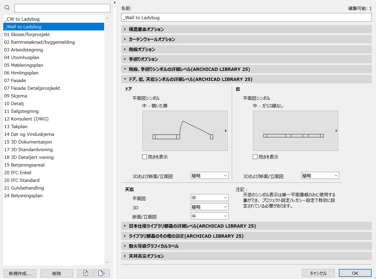
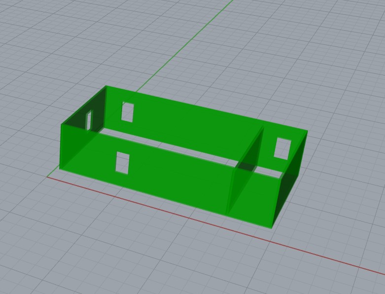
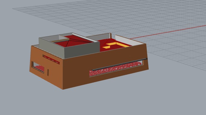
Have you double checked in Archicad to see if the windows are without frames and only a single surface with your settings? Can you post a screenshot from Archicad 3D view with the “_Wall to Ladybug” model view applied? Also can you post a screenshot from Grasshopper showing a “panel” connected from window brep output of the “Deconstruct window”.


The problem of data conversion from Brep to Curve is solved.
As you said, the model display options were not working properly.
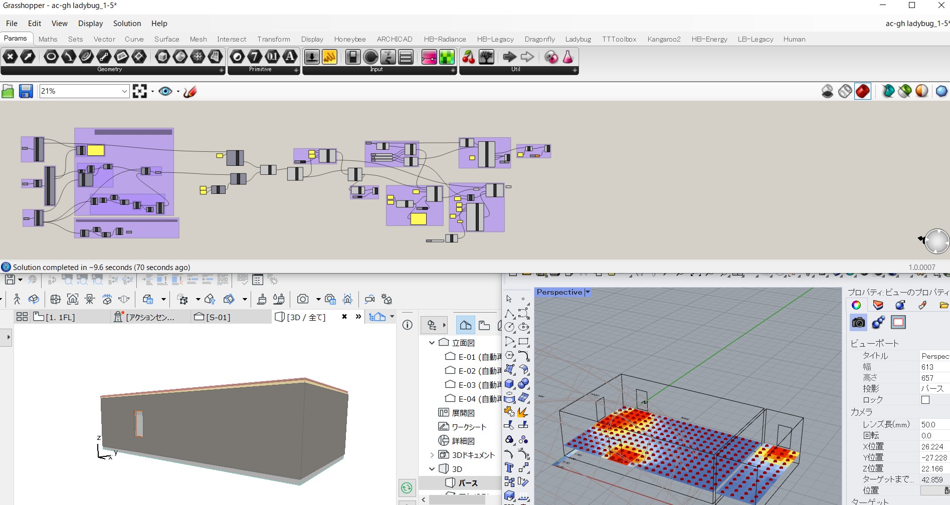
The reason is that the Japanese menu is “detailed”, “simple”, and “scheme”… I misunderstood the meaning of the word. Setting it to “scheme”. worked for me. Attach the model view of ARCHICAD and the screen of grassshoppar.
The simulation is now possible. But there are still problems.
Thermal zone surface offset is in error. Your archicad data didn’t show any errors. I imitated your various settings many times, but I couldn’t fix it.
do you know why? Please let me know if you understand.
Great, this is progress!
Can you send me your archicad file so I can take a look at the offset problem?
1 Like
Ok, try this. I havent worked with thermal zones, just understand the logic.
You have might have to use the polygon from the zone instead of the wall. But it creates too many polygons as the number of zones and number of walls does not match.The offset distance taken from the wall thickness will also be dependent on where the reference line for your wall is (outer edge, inner edge, outer core, inner core).
So this method is not solved Im afraid. As you can see I have not connected it to anything, as its not completed.
1 Like
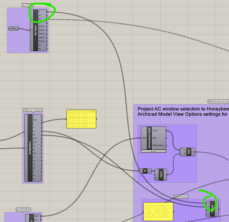
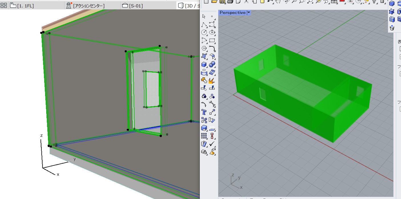
Good morning, I removed the Boundary by connecting the structure and offset directly.
The Rhinoceros model hasn’t changed from before, but the error finally disappeared. It’s so simple and the grasshopper view looks so good!
Thanks to you, I was able to stand at the starting point. Thank you very much.
I’ll keep the files. Hope it helps someone.
ac-gh ladybug_1-5_0827.gh (88.5 KB)
1 Like
@joimagg
I am rereading your comments. The wall seems to be able to reflect the thickness when looking at the finished data with the method you gave me.
What are you afraid of? let me share.
Also, I still have some concerns.
I want to know what’s different between your wall and mine. The reference line is set to the same “inside” as you. I’m trying to make sure the zones and windows are in the same position as your data… Why is it so.
Hey, Kaori, Im not quite sure what you are asking about in your last post?
Your previews from archicad and rhino look similiar as my model.
In “real” projects I will not be able to use the wall reference line as an offset origin because we always have it set to “core inner”. When I would offset with the wall thickness number the thermal zone end up outside the outer wall because there are wall layers (gipsum, insulation etc) going inwards from the reference line.
Using the zone boundary as an offset origin should be more correct, that polygon is always aligned with the inner most layer in the wall. But walls might have different thicknesses and its gonna take a more complex routine/script to offset each side of the zone the correct amount in relation to each wall.
@joimagg Sorry for being late.
i was trying a lot.
And you were right. It was difficult to deal with the complex walls of the actual project.
I came up with the idea of not doing the offset in the first place.
Earlier, in ARCHICAD, we merged all Zones, Walls, and Door Faces to the Wall Reference Line.
And projected the face of the door in your way.
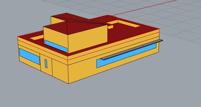
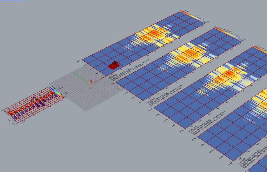
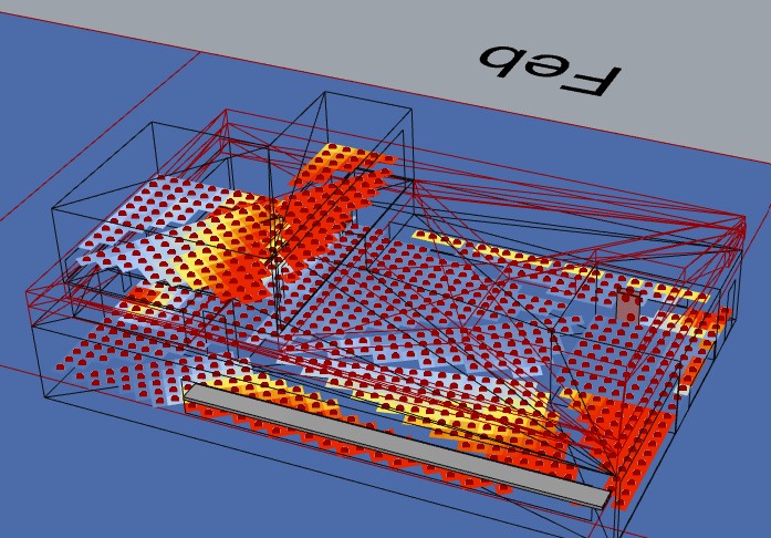
As a test, the radiance and energy simulations for a project with 5 rooms worked.
I’ll post again when I’ve sorted it out.
1 Like
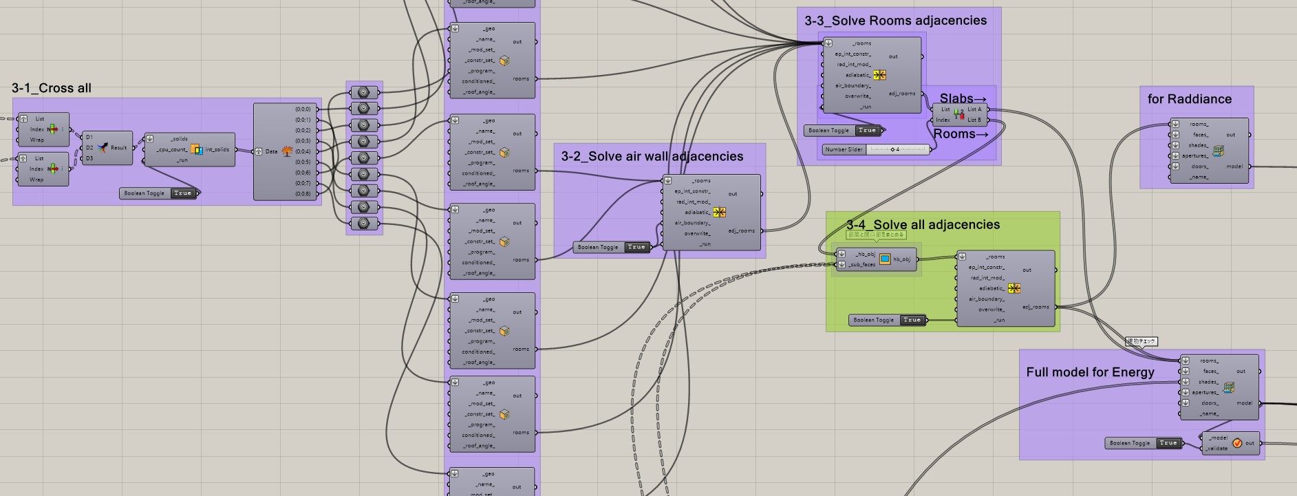
I’m a little worried, but I managed to finish it
AC-Grasshopper live connection use Flow
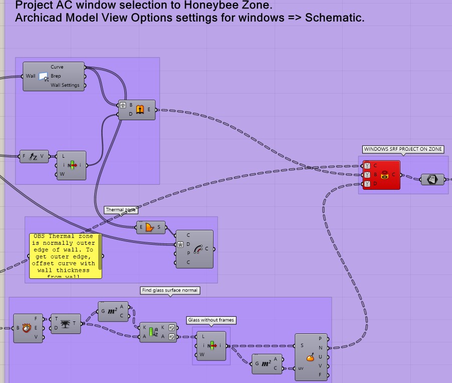
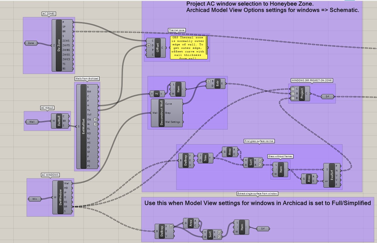
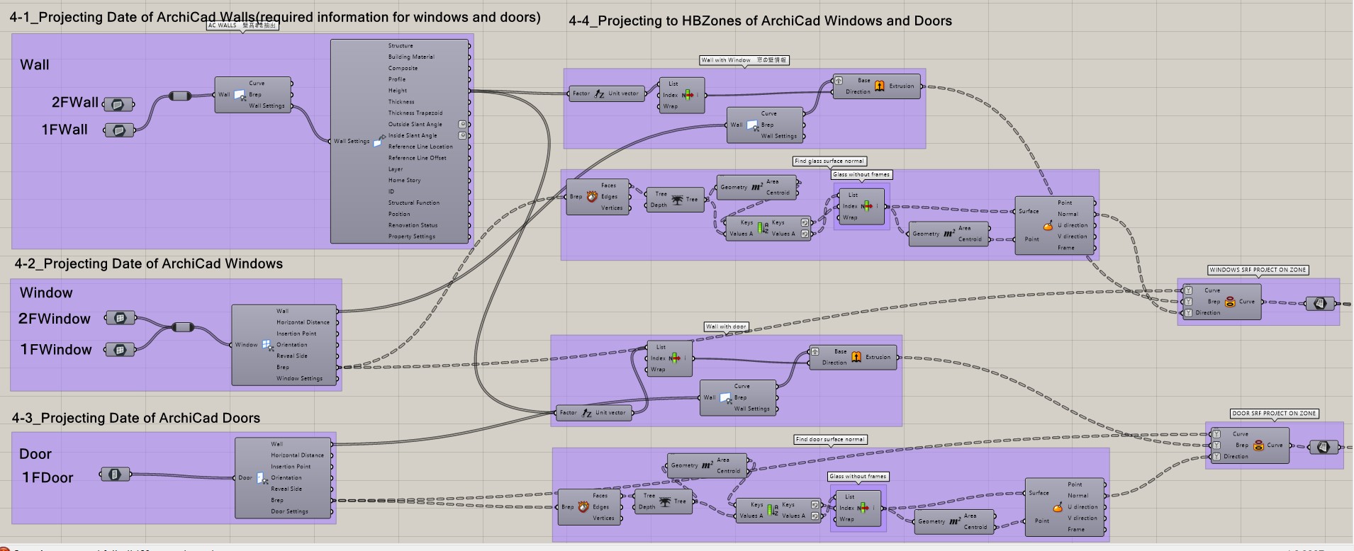
Project Archicad selection to Honeybee Zone.
Preparation for Archicad
0-1_Archicad Model View Options settings for Windows and Doors => Schematic.
0-2_Archicad zone with the center line of Walls
0-3_Archicad Windows and Doors Surface with the center line of Walls
See the diagram for more.
Please let me know if it’s simpler Method.
Would you have been able to stand on the same field as everyone else?

1 Like