Problems with Custom Construction Sets for simple windows NOT connecting to a building model

Kia ora koutou

I have a behaviour in a construction set that I do not understand. The simple window material that I have created is being accepted into the construction set, but is not turning up in the model (I have confirmed this by opening the EnergyPlus Model, but also through visualise the model/room checks.

First, using the LBNL Window Program (THERM 7.8 / WINDOWS 7.8 | Windows & Daylighting), I have defined the thermal and lighting overall properties of a bunch of windows, such as this Triple Glazed Aluminium Frame with Thermal Break, Low-E, Argon filled example:

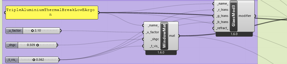
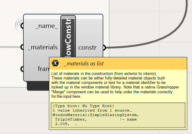
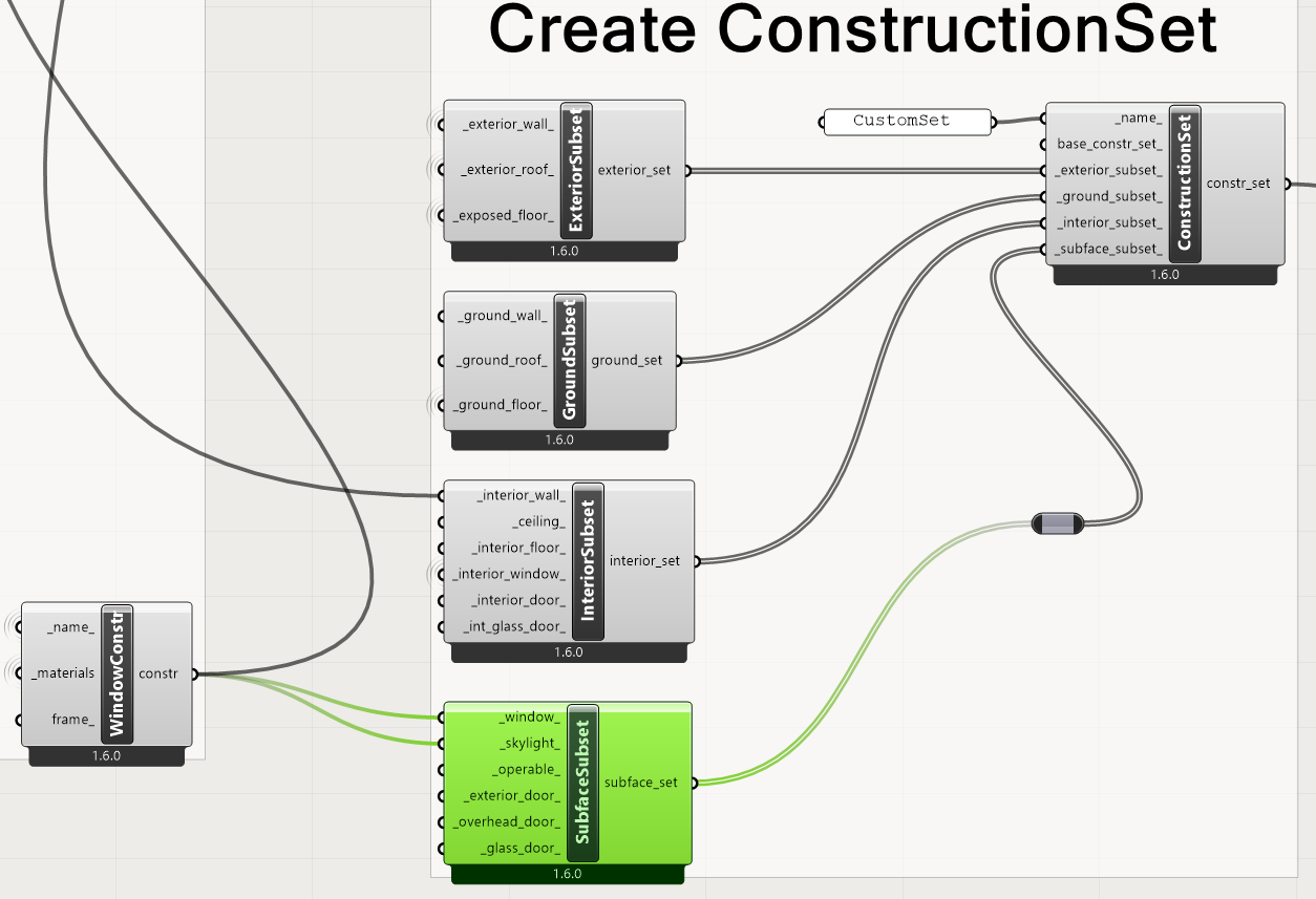
This is then connected to a window construction component:
image

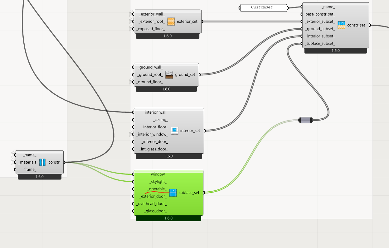
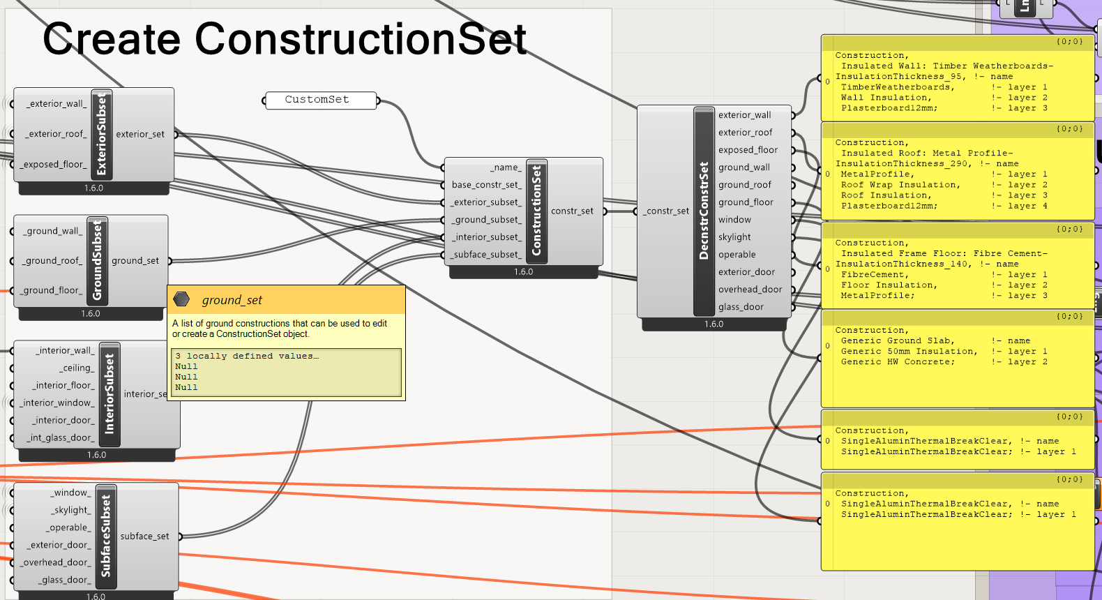
This then becomes part of the construction set:

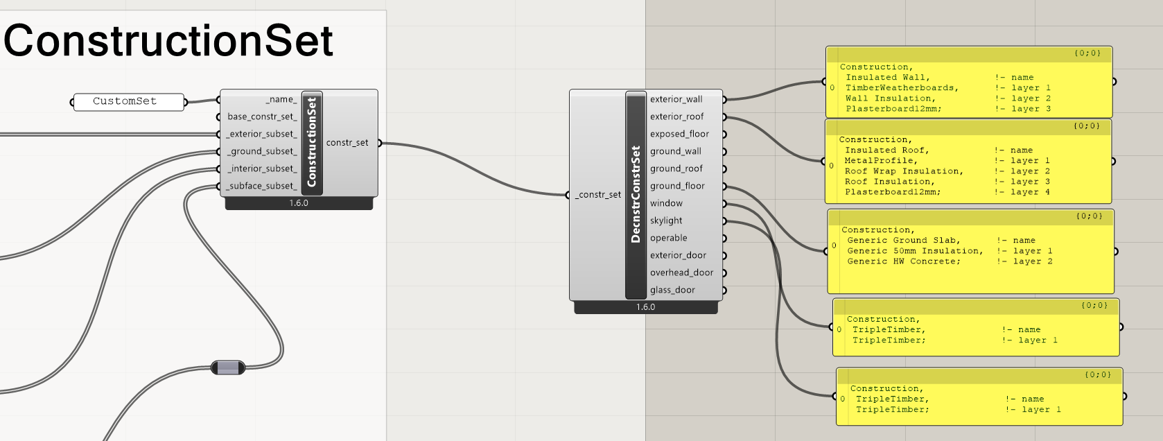
And the construction set deconstructed reveals that the Triple Timber data is part of the Construction Set:

This is then fed into the component.

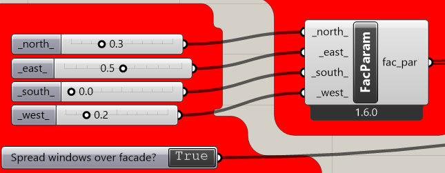
But, after the windows, louvres and skylights are added, it would appear that this E+ construction data is lost.

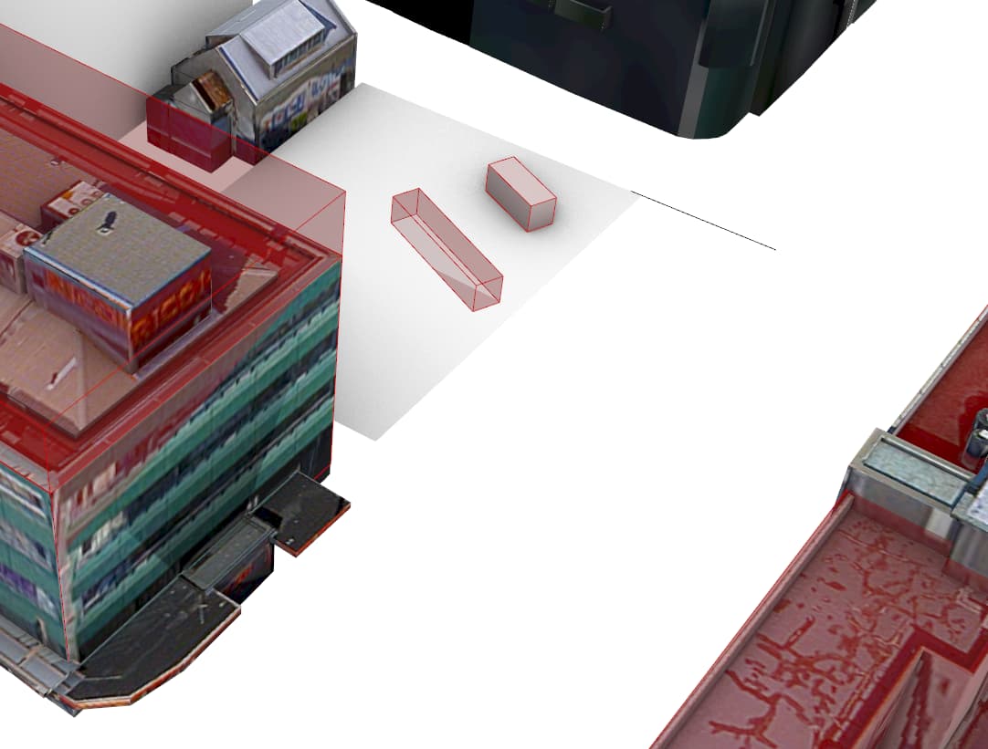
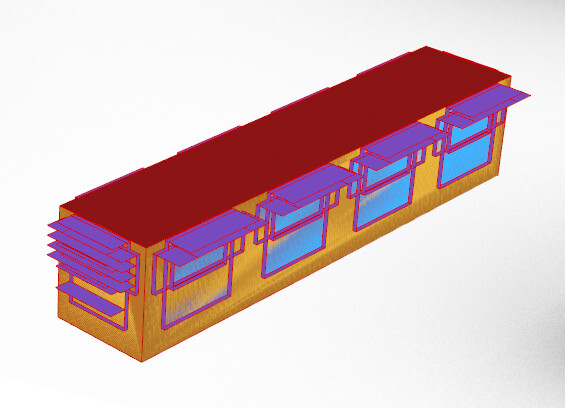
Visualisation of the model reveals this:

This is not what I entered for the windows, though it appears to be correct for the other building elements. I am at my wit’s end trying to decipher this.

HELP!
TEST_2023.gh (630.6 KB)

Hi Mike,

As mentioned to you over DM, the problem lies within the ApertureByRatio component. For whatever reason, when creating the windows, it is not drawing from the construction set belonging to the zone but is rather creating it with the default generic constructions. I have not checked in the coding whether it is overriding the construction with the generic, or simply ignoring the customset, but regardless, it is an issue. @chris This may be an important one to note - perhaps was something pushed out in the latest release, or a bug in Mike’s specific version.

The workaround for this, incase others come to the same problem later, is to use the ApertureByGuide component instead and make your windows using that. Note that the guide surface needs to be close to, or exactly, the surface of the wall you wish to add a window to. This can easily be done with “ExtractSrf” command in Rhino (just remember to specify it to copy the input, not remove it from the solid).

Hope this helps.
Elly

Kia ora @ElzineBraasch

Excellent. Gr8 insight!

I have a small challenge for @chris in solving this issue.

In order to be sure there are as few inexplicable glitches for users as possible I have insisted the 360+ users of my script, who use many different windows and Apple computers, that they all update version to 1.6.24 …

With the corporate, university, computers locked down, with first year students using their own computers, this is the only way to manage the incompatibility of versions (I found a bunch of first year Apple computer students in tutorial yesterday with versions 1.6.51, 1.6.you, and 1.6.74,)

M

Hi @MichaelDonn ,

This is quite the beast of a Grasshopper script but I can explain why the window construction you have added for fixed windows and skylights is not applied to your windows. It’s because I see the script is set up to make all of the windows operable:

Operable windows have their own input for ConstructionSets:

ConstructionSets are built this way because operable windows typically don’t have as good level of U-Factor insulation as fixed windows, given all of the framing that helps make them operable. So they are separated from fixed windows in ConstructionSets.

Long story short, just also apply your window construction to operable windows:

Then, the window construction will be applied:

Repeating my heartfelt thanks.

I realise (after thinking overnight) that this Rhino ExtractSrf will work for the script that starts with geometry drawn in Rhino, but not for my other script that generates models from a plan with no 3D drawing in Rhino.

The script exemplar (for those 3rd year students building their own scripts) starts in Rhino like this (Three zones drawn as 3 surfaces on plan).

There is no 3D brep to extract a surface from.

Depending on what you select from these options:

You will choose a 3 Zone building:

OR (after using ):
Auto-generating Core and Perimeter zones…

But, as I showed in the simpler file for the 360+ students in first year, there is geometry that I might use to ExtractSrf

HOWEVER, even then, if I select all four walls as guide surfaces, the normal array of 4 ratios of each side of the building is not able to be fed into the guide surface aperture definition because it only accepts one ratio. So feeding the array creates 4 copies of the room! :wink:

image

image

So this:

…must be revised to accommodate each wall being treated separately. But, if I do that, then the freedom for the students to rotate and move the shipping container base around on the site, and the interface talking about North, East, South and West facades becomes moot. I can see how changing to sliders for Wall 1, Wall 2, Wall 3 and Wall 4 could be done, but the focus of the interface (the sliders highlighted in RED) on Passive Energy Design issues is lessened. Given 2 weeks investment in getting 360 of them exploring the influence of insulation, glass, shading, orientation from an energy, temperature and good daylight point of view, I might, for this year’s class have to accept that the glazing insulation value will not be legitimately modelled.

Ka pai @chris

Thank you so much. I can fix this. However, the logic of allowing students to make the windows operable or not will require yet more Stream gate / stream filters! An even bigger beast.

Much of the “Beast” is a library of materials included in each script that is based on the library of New Zealand materials that @ElzineBraasch developed during her Masters (The feasibility of 'Building Performance Sketching' within the building design process) . In future, I’d like to go through the process of registering this stuff with Open Studio. But that will require some funding to do properly with local regulatory authority’s support.

The ambition was to allow students to focus on the relationship between the input parameters and the performance.

I am now focusing on another issue to do with the construction set definitions I am using.

Generic Slab Floors seem to be applied automatically, instead of the exterior suspended floor system I would like to offer as an alternative.

Choosing a slab on grade option from my inputs
image

Produces this output from the construction set

And this model:

BUT choosing the suspended timber floor option, produces this:

Even though the floor construction has no input from the ground floor subset.

And this, persists even if I remove the ground subset…

Hi @MichaelDonn ,

Your screenshots seem to show the expected behavior. When nothing is connected for the _ground_floor_ construction, it will use the Generic one. Can you elaborate more on what you were expecting?

I have set the script up to allow a choice for the construction of the floor.

Either it is a suspended timber floor (connected to Exterior floor) OR it is a slab on ground where I have set up material choices as input for concrete thickness and an amount of insulation.

If I have no ground connection input to the ground subset, or if I disconnect the ground subset altogether, the construction set still seems to ignore the exterior floor construction and applies a default slab on ground to my one floor in my simple box building.

I am sure there is some simple logic that I have missed despite the excellent self documentation that the LBT components have (as with the window construction)

Thanks for the follow up.

M

Kia ora @chris

I think I may have broken the chain of submission / response by editing my original question about the thermal construction sets Problems with Custom Construction Sets for simple windows NOT connecting to a building model - #6 by MichaelDonn to clarify the question rather than resubmit all the graphics.

BTW: on reflection, I like the 3 different window types for the . I can see making the Frame / Mullions modeling more explicit over time, even though the international standard approach to Window R-values is to create a rating based on a standard window size.

I can see building the capability over the upcoming summer to allow for different framing systems and window sizes in an energy / lighting and upfront carbon facade analysis tool. I was pleasantly surprised to realise there is the opportunity to alter both the thermal and the lighting material properties at this subface subset level to differentiate glazing properties for openable and fixed windows and for skylights… NICE

Still puzzled by the inability to have exterior floor construction over-ride the slab on grade construction.

M