I’ve been trying quite a while to make the attached to work but without success.
It started as a section that included part of a wall. Now i took out this part and left only the window.
The HB_writeTHERM complains about:
Geometry connected to _polygons does not have a single boundary (there are holes in the model). You will have to fill in these gaps when you bring your model into THERM.
I can’t see where these gaps can be. Tried the dupborder check, but nothing.
Opening the created therm file in THERM gives me:
There are points in the model that are closer together than the program tolerance.
But also there i can see where is/are the faulty geometries.
Will appreciate any help here to understand what i’m doing wrong.
You were on the right route to getting your issue solved. When you join all of your polygon surfaces together and use the dupborder command, you should be checking to see the number of borders that get produced. If it is more than 1, then you have a hole in your model. Here is how I checked for the hole in you model:
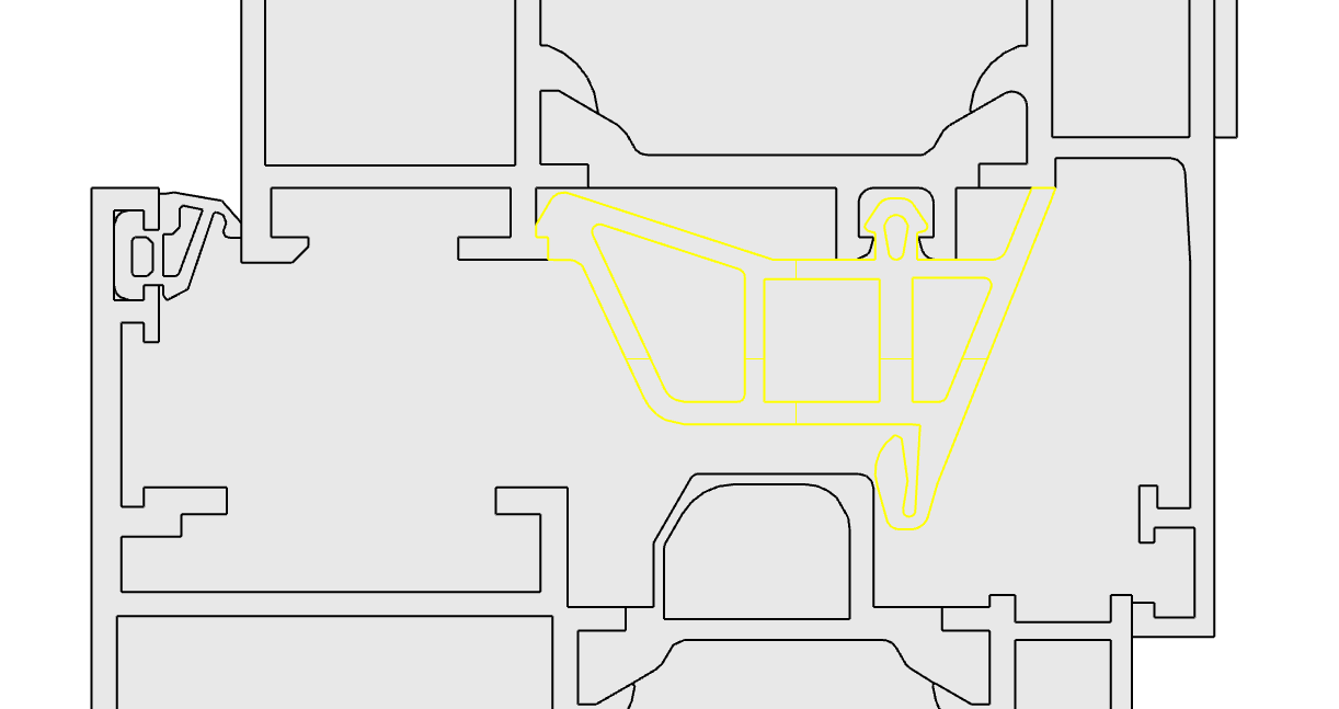
Note that the hole can be really small and I had to deselect the outer border with Cntrl+left click and use the “zoom selected” command to find your very tiny gap here:
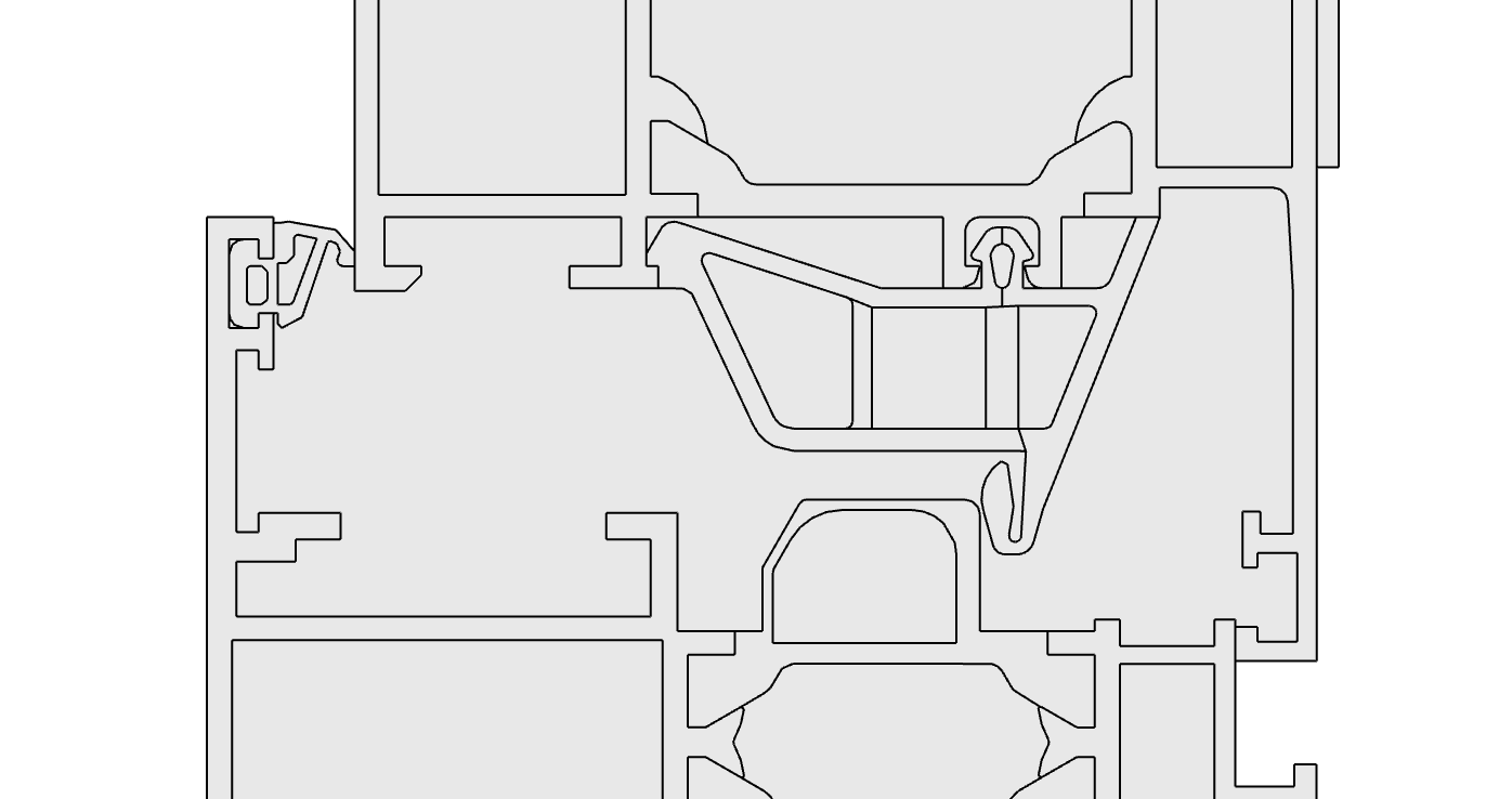
To get rid of the gap, I deleted out the aluminum surface next to the hole, joined all of the polygons together, ran a dupborder command, and used the curve around the seleted aluminum surface to build a new surface with the PlanarSrf command (this ensures no gaps). Then I brought all of the new aluminum geometry into GH, connected it up to the THERM components, and it ran the export component without and issue. When you open the file in THERM, you will sometimes get the following message:
In this case, you should ignore it at take the default option (Mark the points but don’t adjust them). The reason why this error happens is just because there are no other CAD plugins for THERM and the software still freaks out whenever it recognizes that the geometry has not come from its own interface. After you simulate, you can bring your results back into Rhino/GH like so (and see attached):
I know that this seems like a lot of clean up work but trust me that this is far less than what it used to be when you had to build models from scratch in the THERM drawing interface.
I was getting crazy with this. Specially since i built the polylines in Autocad and imported. Now i see that one of them had a “double line”.
May i ask another one for the same case? From the HB_readTHERM i expected to get the uValues for the 4 boundary curves i defined in the input (I changed the input tags to List type, and now back to item, if you use the same fixed file). Instead i get only one of them (the frame). For some reason Therm don’t get the other 3 boundary curves.
You had been assigning the U-Factor tags correctly and I have added in a message on the thermBC component that lets you know that this is happening. The reason why all the tags were not showing up is that the glass polygon needs to have vertices that align with the endpoints of the therm BC line segments in order to be written into the thmx file. You can see that I have done this in the attached file by generating the glass thermPolygon from a polyline that has vertices that align with the thermBC endpoints.
I had been thinking of writing a check in the writeTHERM component to automatically split the polygons using the BCs when it sees that the BCs are not aligned with the polygons but it was increasing the calculation time a lot. Perhaps I’ll put this in but I’ll make it optional.
Whatever you can do to ease the process will be blessed. Right now i’m using your definition, cause when i tried the insertion points is still not recognizing them. Sometimes i missed the exact location (not well aligned), but after fixing them (i think) … no luck. For now i have to finish a presentation for class, but tomorrow i’ll let my version a try.
Something happened now the messes the legend. I updated today the ThermBoundary component and right after that the legend is scrambled. See image. I assume that things are related.
The previous issue appeared again and now i can’t make it dissapear (messed legend). I can’t say what i did to make it happen, so i don’t know where to point a finger. Just can say that it started when the ThermBoundary component was updated.
After the previous paragraph, I copied from another file a previous version of the component and the legend was fixed. Switched back to the updated version and it is working now.
I am also modelling a window section and I got an issue. I modelled the window frame with polylines and then make them as a surface. After I assigned the materials to the right surfaces and run the simulations I got an error like “Geometry connected to_polygons does not form a single polysurface” and there could be holes as well (even though I have already drawn 3x this one). I baked the Therm_polygons, join them together and I checked with the “DupBorder” and it says I have 1 border which would mean that there is no hole, so I dont know why i got these errors. Can you help me to figure out what the problem would be? I would be very grateful :).
I attached the rhino. and gh. files. window_therm.3dm (1.1 MB) window_therm_gh.gh (505.1 KB)
Why don’t you try the probRegion output on Honeybee_Write THERM component to find out problematic edges? There’s typically some difference between what we think is fine and what the tool thinks is fine.
I took a quick look at your file and I can see that the issue is the result of two things, which become apparent by checking the probRegion as @devang suggests :
You have a number of polygons with holes in them going into your simulation and, while honeybee supports this, THERM does not allow polygons with holes in them.
The code that I wrote to automatically split polygons with holes into shapes that do not have holes is honestly not that good and it’s prone to errors. For that, I am sorry and I can at least say that I have thought of a better way to handle this when we eventually implement THERM capabilities in the [+] plugins.
But such [+] components are still a long way off in the future, and so I have a simple workaround for now, which is to manually split each of the polygons with a hole. So, you can take a polygon like this:
This will at least get the export of the model to THERM to be clean.
I will give one other note of caution about an issue that is beyond my ability to change myself but the THERM meshing algorithm has some limitations in terms of the amount of detail that it can resolve ad is especially prone to failure when there are large jumps in detail. I can see that you have a lot of detail in your model that is beyond what is needed to get a sense of the heat flow through the construction. So you may need to change this model to be a coarser representation of these details in order to not have the THERM meshing algorithm fail. Narrowing the size of the detail you are studying will also help.
Thank you so much for your reply. With your advise I could do the simulation. I made the whole details a little bit smaller and I turned the complex parts into simple. Also whenever I made a new part I checked whether is good for the sim or there is a problem so I modelled the whole detail step by step, and now it works. Thank you so much!