Hi, I am working on project of simulating PV energy output when this PV panels are mounted on Different building facade orientations ( east, west and south). My question is why I get the same energy output results in case of I picked pv surface ( with x m2 area) mounted on south facade and the other case when the same PV area mounted on building east facade ? Logically The results should be different when I change PV orientation ( facade ) … Thanks in advance for helping…
Hey @RadwaEzzat ,
I have no idea which components you are using. Are they they legacy Ladybug “Renewables” components?
Yes I am using renewable energy component. In another words, my question is how to include PV panels orientation on simulation ( make ladybug feel that the PV panels is mounted on south or east or any other facade orientation) , and also how to include shading effect of building parts on pv ?
The author of the Legacy renewables components is @djordje and he might be able to answer.
Otherwise, I can explain some methods for estimating harvested PV electricity with the LBT plugin.
Hi @RadwaEzzat ,
Can you attach your .3dm/.gh files please.
Thanks MR djordje for replying. I think I find the problem. Now I need your help to complete task. Here, as I illustrated that I work on tracking PV panels mounted on building facade, then I need “tilt angle” and “azmuith angles” parameters to be added to the chosenPV surf, but at the same time I dont want to use “LB PV syst Size” component as it has mant parameters I did not need and it cause problems in final results, so could you help me editing “LB PV Surf” component and adding “tilt angle” and “azmuith angles” parameters to it directly? I think it need to edit component script and actually I did not have any experience in writing or editing scripts or codes? or could you suggest any other components to be used for adding these tow parameters to the selected PV surf ? I wish you could help me. thanks djordje.
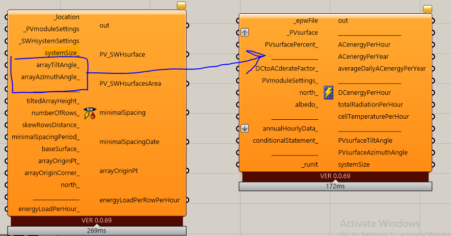
djordje I also think about making anew component/ script consist of the inputs (PV sur, PV tilt angle, PV azmuith angles) to get the output (PV SURF). Could ypu help me plz?
Hi @RadwaEzzat ,
I can’t modify/create a component on a such individual ad hoc basis. The current components have been created to fit into the Ladybug Photovoltaics group of components.
You can do it yourself if you want to, this is one of the fantastic features of Ladybug components - the code is open-source, and you can addapt it to surve your needs.
I would advise learning python first. There are multiple sources for that:
After that, if you are trully interested, you would have to understand how ghpython components work. Here are Mcneels introduction articles:
Third step would be to understand Ladybug Photovoltaics PVWatts model. Check the references in the following starting post:
If you don’t have that much time, I would simply use the tracking PV definition from Konrad K Sobon:
Thanks for replying, I partially found quick solution but still need help…so, could you please see this topic LB v 0.61 problem
Can you please explain the alternate ways without using Legacy plugin?
Hi @RadwaEzzat,
You might want to check this:
The tools are also available for download here:
Tell me if you need help in using it.
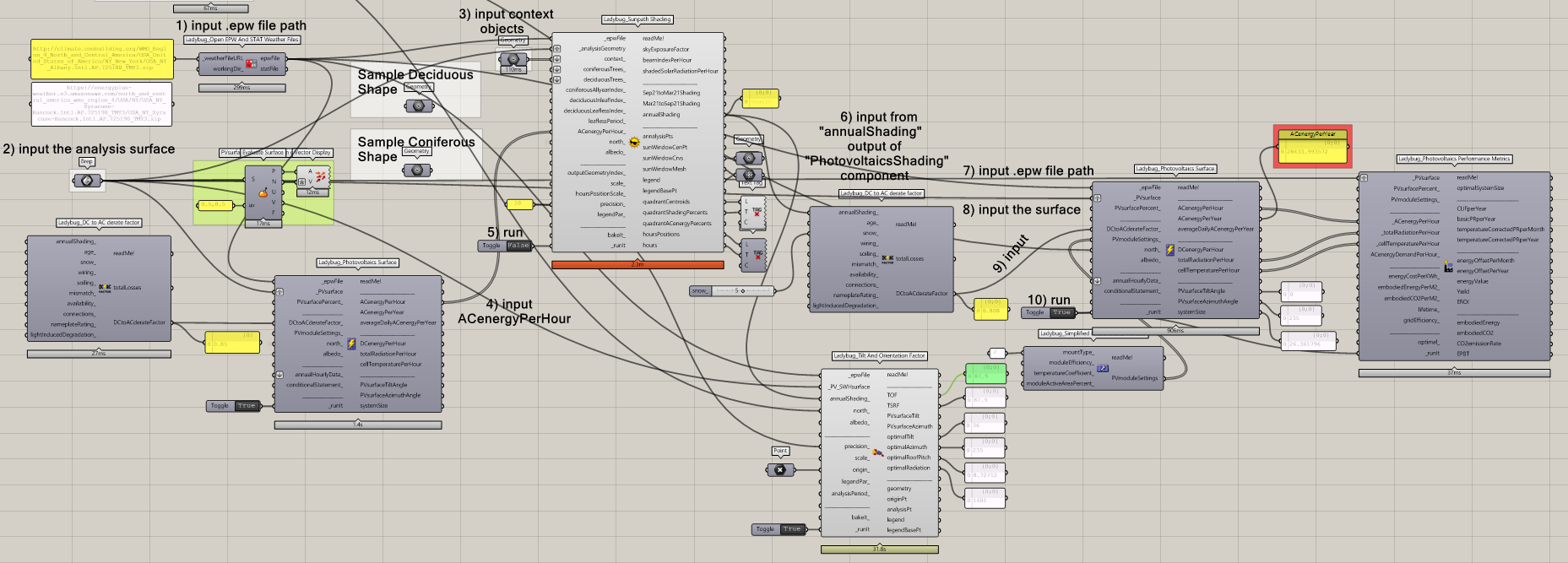
Hi @djordje. I’m using your legacy tools and I started from your sample file with shading.
I’m kind of trying to figure out if I’m doing it right. Can you take a look at my canvas and see if the flow is making sense?
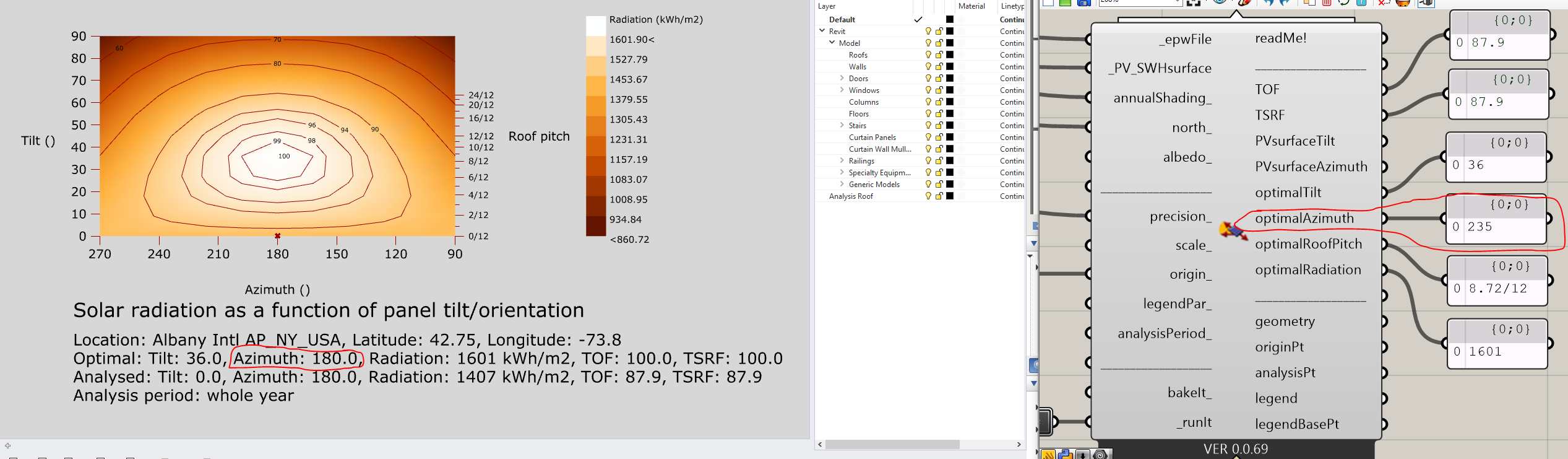
In the second image, I believe the optimal azimuth in the graph image might not be working. (Not that you are going to update LB Legacy, but just noticing.)
Hi @JimMarsh ,
By looking at the components disposition and connectivity - it looks fine.
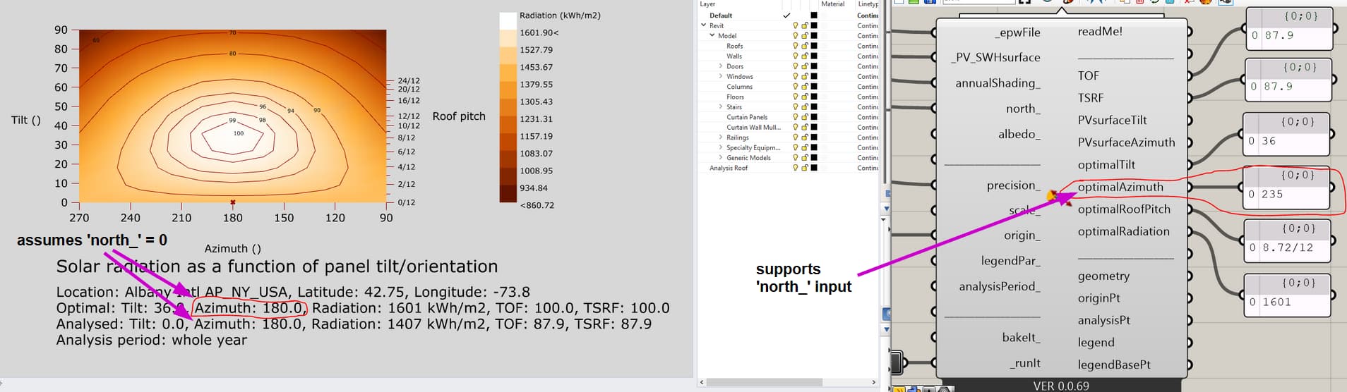
As for the optimal azimuth: I probably never added support for ‘north_’ input to legend description. So the legend description will always act as if ‘north_’ input is 0 degrees.
But you can rely on the ‘optimalAzimuth’ output - because it does support the ‘north_’ value:
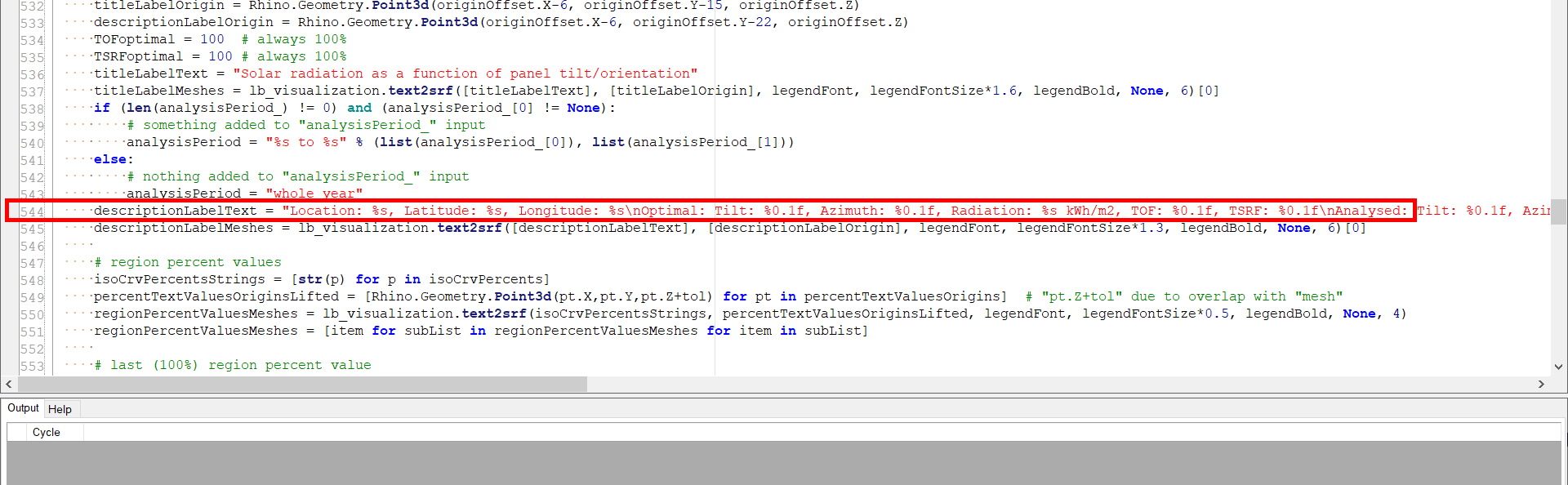
If you would still like to correct the legend description, double click on the ‘Ladybug_Tilt and Orientation Factor’ component, and replace the line 544 with this code:
descriptionLabelText = "Location: %s, Latitude: %s, Longitude: %s\nOptimal: Tilt: %0.1f, Azimuth: %0.1f, Radiation: %s kWh/m2, TOF: %0.1f, TSRF: %0.1f\nAnalysed: Tilt: %0.1f, Azimuth: %0.1f, Radiation: %s kWh/m2, TOF: %0.1f, TSRF: %0.1f\nAnalysis period: %s" %(locationName, latitude, longitude, optimalTiltD, optimalAzimuthD+northDeg, maximalTotalRadiationPerYear, TOFoptimal, TSRFoptimal, srfTiltD, srfAzimuthD+northDeg, totalRadiationPerYear, TOF, TSRF, analysisPeriod)
Thanks for the review. I was a little hesitant about using the Derate Factor before AND after the calculation, but the sample file had it set up that way, so I kept it.
@JimMarsh ,
Yes, you should use it like that before - and after. The only difference between two should be the “anualShading_” input for the “after” component. So make sure that all other input values are the same between both of them.
Ok, that makes sense because the first one would not have any “annualShading_” to input.
I guess I understand it as:
- The first node gives the PVs a derate based on manufacturer or general knowledge.
- The second node is only using environmental factors to derate the PVs because node 1 has taken care of the general derating of the panel itself.
Hi @JimMarsh ,
I found formulate it like this: second component should take into account “annualShading_”. While the first one does not. So this should be only difference between the two components.