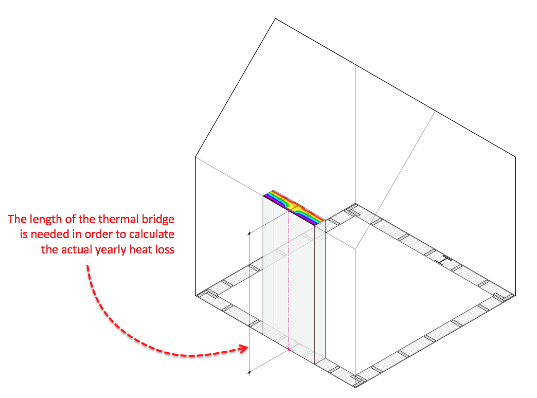
In case anyone would find it useful, I thought I’d share a recent attempt to use the Honeybee THERM tools to calculate simple ‘Psi-Values’ for a couple of example scenarios. I’ve added just a few new components (file attached) in order to allow you to do this based on the U-Factor results which are compiled by the THERM components. These calculations will produce linear thermal bridge heat loss values (in W/mk) which can then be applied to an energy model such as through the Honeybee E+ tools. Note that in order to do this you’d also need the ‘Length’ of the thermal bridge in the actual building in addition to the Psi-Value generated here:
All calculations here are based on the ISO 10211 methods and default values / boundaries. The PSI-Value is just the difference between the actual heat loss (from the 2D simulation) vs. the assumed / predicted heat loss from the 1D U-Factor method.
All calculations here assume using EXTERIOR dimensions for the U-Factor clearfield 1D heat flow.
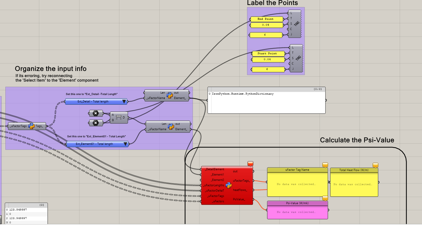
In order to get the calculator to work, you just need to hook it up to the standard ‘readTHERM’ Honeybee component and a few additional inputs which describe the 2D ‘Idealized’ lengths. I did that by just inputing 3 reference points which works for most situations but certainly there are lots of ways this could be done.
I didn’t do a ground calculator - this only works for ambient air situations.
All the simulations are using ISO 10211 default temps (20°C interior, 0°C exterior) but it should work with whatever temps you input.
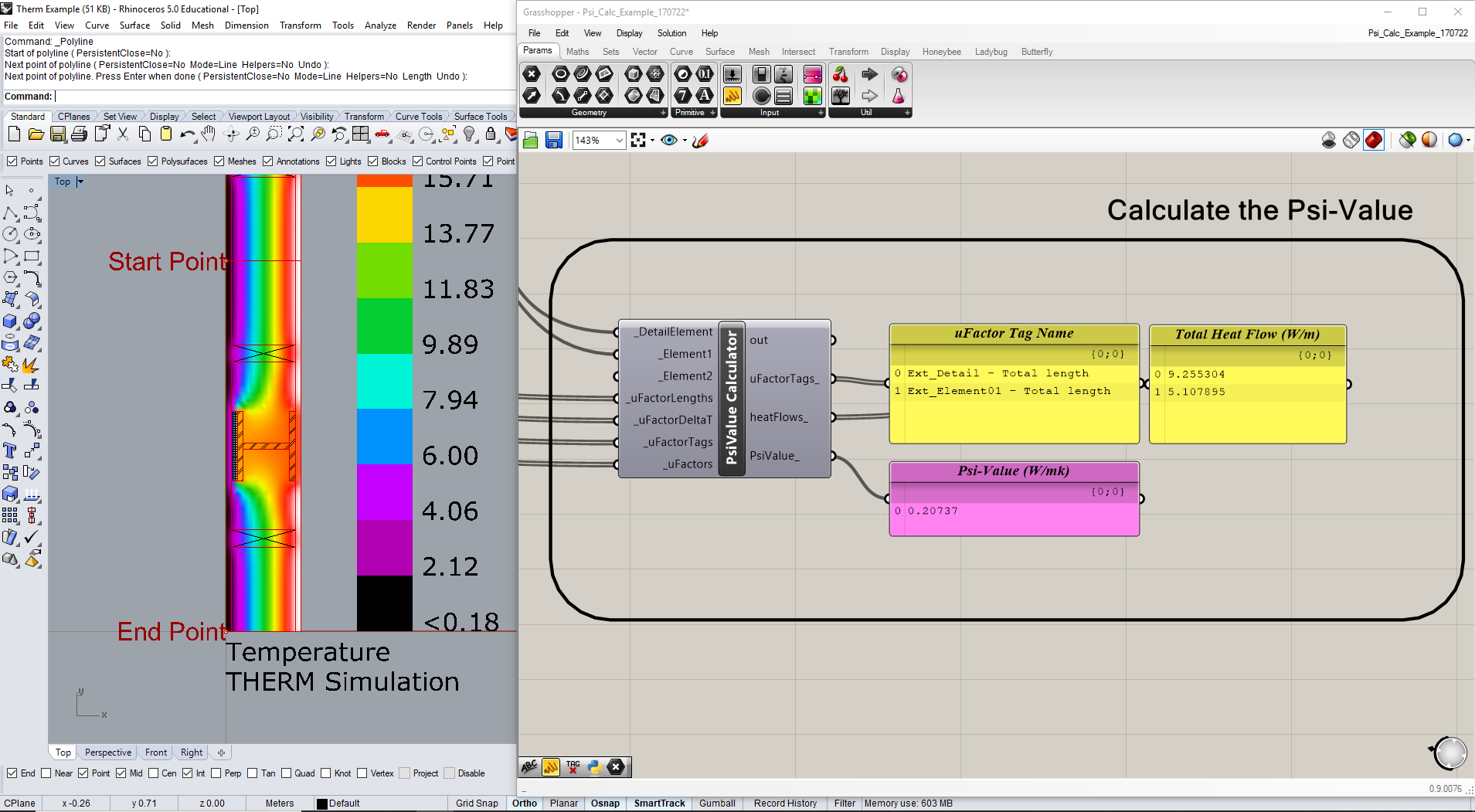
1-Element Example:
A plan-cut of a 2x6 wood stud wall, insulated but with a steel W-section column inserted (with 1" XPS on the exterior). Gives a Psi-Value of +0.20737 W/mk (for reference, in ‘Passive House’ construction we shoot for <0.01W/mk for all thermal bridges)
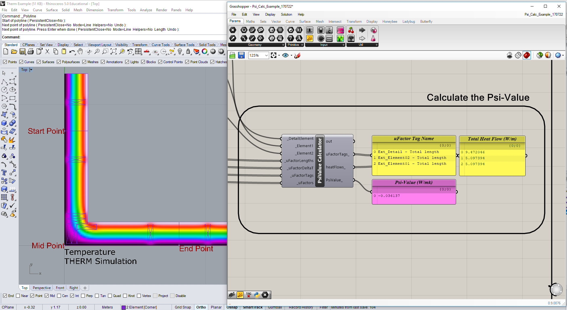
A plan-cut of a 2x6 stud wall turning a corner. These ‘geometric’ thermal bridges typically yield a ‘negative’ Psi-Value when using exterior dimensions for the clear field inputs. This example shows a Psi Value of -0.036137 W/mk which is as expected.
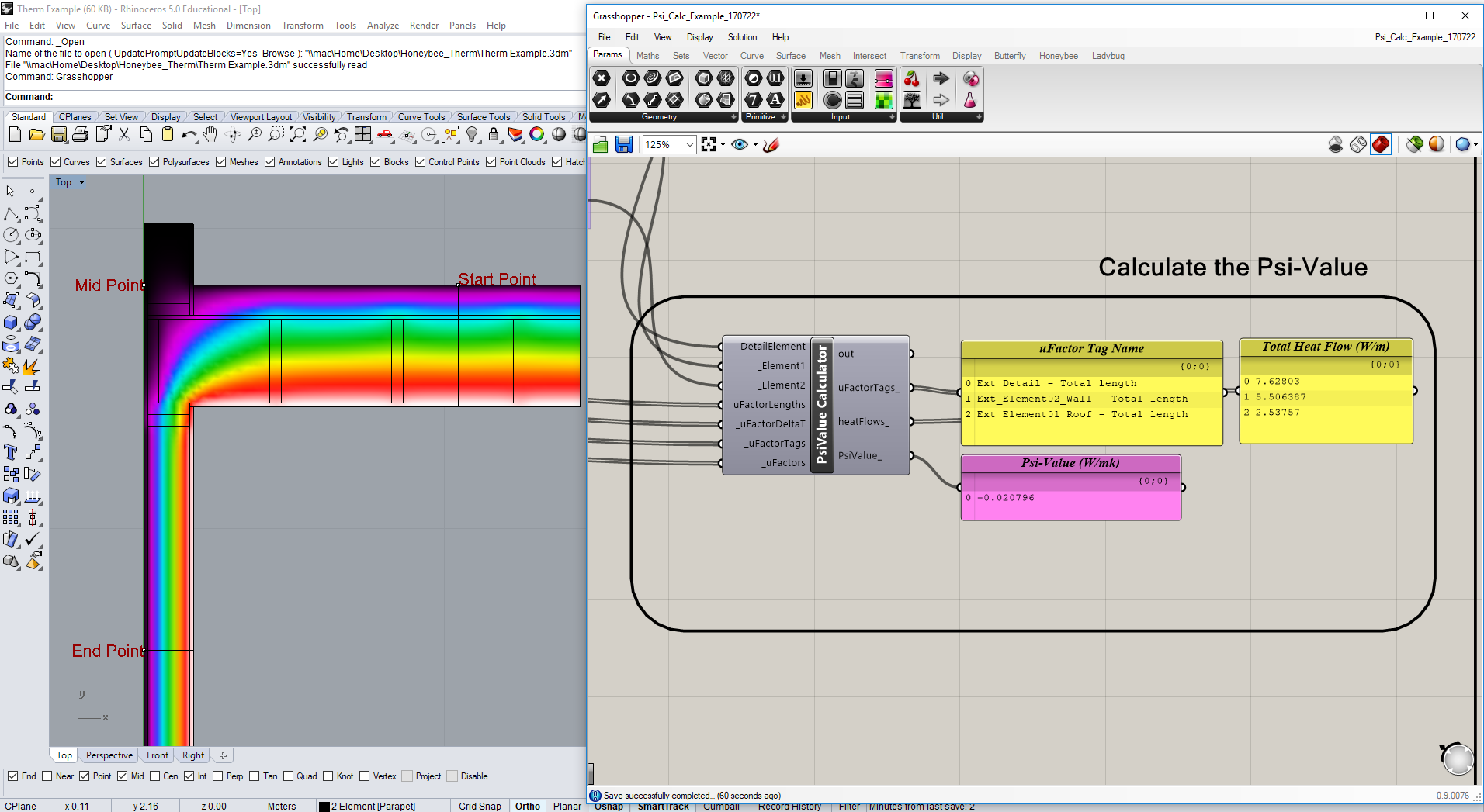
2-Element [Parapet] Example:
This one shows an example of a section cut through a typical wall-to-flat-roof / parapet detail where the exterior BC length is very different and irregular. As with the rest this method assumes ‘exterior dimensions’ for the inputs and Psi-Calc. As with the other 2-Element example, inverted junctions will typically yield a negative Psi-Value when using exterior dimension references. This one calculates to -0.020796 W/mk.
anyway, I just thought someone might find those components useful or of interest. Note that I don’t think E+ can accept the ‘negative’ Psi-Values (might be wrong about that?). But if you are using a program like PHPP or WUFI you can input those negative values to take credit for the reduced heat flow at those inverted junctions.
Also - be sure to set your ‘Units’ tolerance in Rhino to 0.0001 before opening the .GH attached file here to make sure you don’t get any errors.
@edpmay ,
There’s a lot of great stuff here and thanks for sharing.
I am not nearly as familiar with the methods for calculating Psi values as they rarely get used over here in the US. Your post and you example here helped me understand a lot more about how these values are calculated and I learned several things. For one, I didn’t realize that the idealized construction that the thermally bridged construction was being compared to could also have thermal bridges within it. There are definitely some changes to the Honeybee Therm components that should be made as a result of this.
Firstly, I’ve realized that we should integrate the UFactorLengths and the DeltaT into the “Read Therm Result” component. I never realized that these pieces of information could be so useful but your file clearly shows that they are important for calculating total heat flow, which can be important for this among other cases. I have added this as an issue here:
If you want to try to add this into the component yourself @edpmay , I will gladly accept a github pull request from you with this addition to the Honeybee components (and then you will get credit as a contributor on the github). Otherwise, I can add this code in and just credit you for the addition at the top of the “Read THERM Result” component.
Secondly, It seems valuable to have your component that calculates the Psi value and total heat flow as a part of Honeybee but I feel that there may be more elegant ways of doing it. Can you think of any cases where we would not have the element length from the BC length and so we would not have to use the two points to define the length? Or is the idea that the element lengths are supposed to be projected into a specific plane for the simulation?
Thanks again for doing this @edpmay ! I’ve already learned a lot.
@jwoodall ,
Just change the name of the workingDir and the fileName on the “Write THERM File” component. You probably just don’t have those folder locations on your computer or you don’t have permission to write to that location.
Thanks guys - I’m glad to you thought this was interesting and I hope its helpful to folks.
Yeah unfortunately in the states there are very few good guides for calculating Psi-Values and its not addressed much outside some pretty specialist disciplines. It was only really once we started doing projects to European certification systems such as ‘Passive House’ that we began to wrestle with these calculations more. Even so, there are really not a lot of good resources for understanding the protocols and calculation procedures for these - so its taken us a while to sift through the ISO standards and examples try and understand the rules.
I think that part of the confusion as well is that those of us in the building performance industry often talk about ‘Thermal Bridges’ and ‘Psi-Values’ as though they are the same thing when in reality the TB is a general concept and the Psi is better thought of as a ‘correction factor’ for the simplified planar energy-model which is used to more accurately account for the heat flow at complex intersections and junctions of the actual construction.
If you are interested, I’ve posted up some PDF’s from some of our recent THERM trainings in NYC. We try and do monthly ‘after-work’ trainings through the NYPH group here in NYC for folks who are interested in these tools since [in my opinion] they are really useful and important for architects and engineers to fold into their workflows. If you are interested you can find PDFs from them online here:
I think they give a reasonably good overview of the PSI-value calculation process for most basic situations. I’ve only posted parts 1 and 2 for now (we have a ‘part-3’ built that shows the ground methods but those calcs are super weird and its taking us a little longer to distill those down into something understandable / presentable).
As you can see in the examples in those PPTs, there are a couple situations where the THERM BC’s won’t align to the ‘idealized’ 1D lengths automatically. In particular for things like the parapet / overhang condition or anyplace where where the exterior surface area is wiggly or irregular. I was trying to think through the ‘types’ of conditions that we run into and I’ve tried to diagram them here:
I think that for the first or second types that yes, the relevant info could likely all be pulled from the U-Factor file and the Psi-Value calculated automatically. But I think that for the second two types I’m not quite sure how to get the calculator to know which elements are which automatically and where they intersect. Actually I guess I could imagine a few scenarios where this would be possible - but they’d all involve the user tagging / inputting the data in a few particular manner and so I’m not sure how flexible and resilient that would be in practice. But I’ll think about it more and try out a couple methods and post here. I definitely agree that making it more flexible / automatic would be important.
As for the components:
Yes if you think this would be helpful to integrate into the HB tools I’d be happy to work more on the overall workflow and try and reduce down the steps / streamline and automate it more. If you are able to add the UFactorLenghths and DeltaT to the basic ‘readTHERM’ that would be a great first step.
For the editing of the ‘readTHERM’ component - I think it would probably be best if you edited it rather than me doing that: I’m not really a ‘code’ guy but rather more on the building-science side - I certainly enjoy messing around with writing code to add/expand but I wouldn’t want to accidentally break anything in there in the real component.
@edpmay ,
Thanks again for all of the information and I have pushed the changes to the “Read THERM Result” component such that you now get the BC length and the delta T:
I also changed these outputs to be a data tree where each UFactorTag is its own branch, which I think will make it a lot easier to process the results for these simulations where you have more than one uFactorTag:
I also decided to bring in all of the tags even when the BC length is 0 and the UFactor is NaN since this will make it easier to write scripts to process the results (since the first UFactor in the list will always be the Total Length, the second will always be Projected X, etc.). At the least, this will save you from having to manually select each UFactorTag out of the list in your result post-processing. In an ideal scenario, I hope that it also means that you might be able to use the projected X and projected Y U-factors in a Psi value component instead of having to manually put in points but I realize there may be a few steps to figuring out how to do this.
Lastly, I added you to the credits on the components for supplying to code to parse out the BCLength and the DeltaT:
Let me know if you get the chance to post an updated Psi value component now that we have these changes. As I said, we’d be happy to have it as a part of Honeybee.
Oh, and @jwoodall , I added a check to the THERM simulation component, which should decrease the probability of you seeing the WindowsError. I have realized the latest versions of THERM seem to be locking the thmx file somehow, which cases errors when you re-run the component. The check in the component should catch these situations now.
Here is a question I’m thinking about for a long time. How are thermal bridges taken into account in HoneyBee and how can we set them in HoneyBee Tools ?
I always specify these values in other softwares (DesignBuilder, Ecotect, …). And not knowing how this works here keeps me from using HB completely.
@chris that is fantastic, thanks! - I’ll take a look at the updated component structure and see how I can revise the Psi-Calculator portion to work more effectively / automatically and will post an update.
@EmmanuelR for Honeybee / Energy+, ‘Thermal Bridges’ are taken into account in two ways:
In the U-Factor any ‘repeating’ thermal bridges from studs or similar items are taken into account in the determination of that U-Factor value (w/m2-k or Btu/hr-ft2-F)
For what are considered ‘construction’ or ‘geometric’ thermal bridges (with Psi-Values, in w/mk or Btu/hr-ft-F), these are not directly taken into account in Energy+ I don’t believe, but you can use a workaround to add the extra heat-loss from these effects into an Energy+ model through the use of an ‘OtherEquipment’ object so that the effect on the zone thermal balance is influenced by this extra heat loss and the energy/load calculations will register this. See here for more info on this method: https://unmethours.com/question/8758/clarification-of-energyplus-otherequipment-impact-on-hvac-loads/
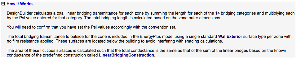
Another method is the way DesignBuilder does it, but as they state in their reference guide, since E+ doesn’t include Thermal Bridge objects by default, some funny business (creating a fictitious wall with the equivalent thermal conductivity) is needed in oder to take these thermal bridge effects into account:
Anyway, I’ll try and add an implementation of folding these Psi-Values into an E+ mode to a more complete example file once I have the Psi-Value calculator working better and I’ll add that here for your thoughts.
I’m trying to learn Ladybug and Honeybee in depth, just started a while ago - this is my first post here.
@edpmay
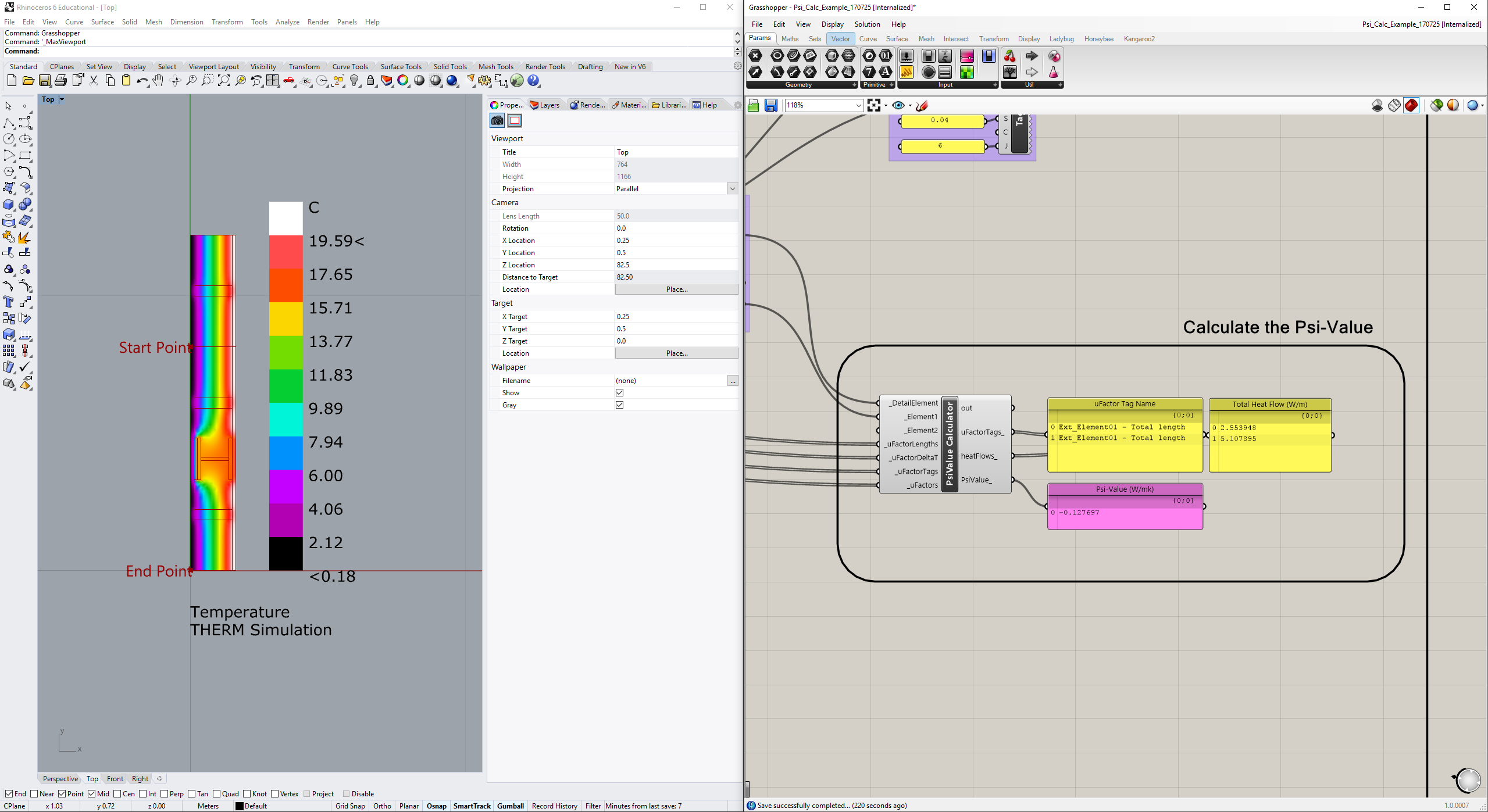
In the first example you posted, there is a Psi value of +0.20737 W/mK (the simple stud wall). I’m evaluating your script, and noticed, that for me it is -0.127697 W/mK.
The heat flow is also different in the first line for the detailed 2D simulation.
I am using the latest Ladybug (0.0.66) and Honeybee (0.0.63), I have just installed them according to this guide:
I’m in the process of learning the underlying physics as well, so I would like to make sure that I can follow along the examples posted here and Hydra, and troubleshoot when I see differences like this.
I was also having the “WindowsError” with the writeTHERM component, which I managed to resolve - changed all the working directories to mine, changed the unit tolerances to the required 0.00001, set the “Save Conrad results file (.O)” in the THERM simulation preferences. It didn’t work. So I’ve quit Rhino and Grasshopper and started it again as admin, this time it worked. Please bear with me, I’m getting used to Windows again, feels like I’m shooting in the dark, I’m not yet confident what I’m doing.
I hope you can find the time to explain my questions.
All the best and thank you for all these valuable resources!
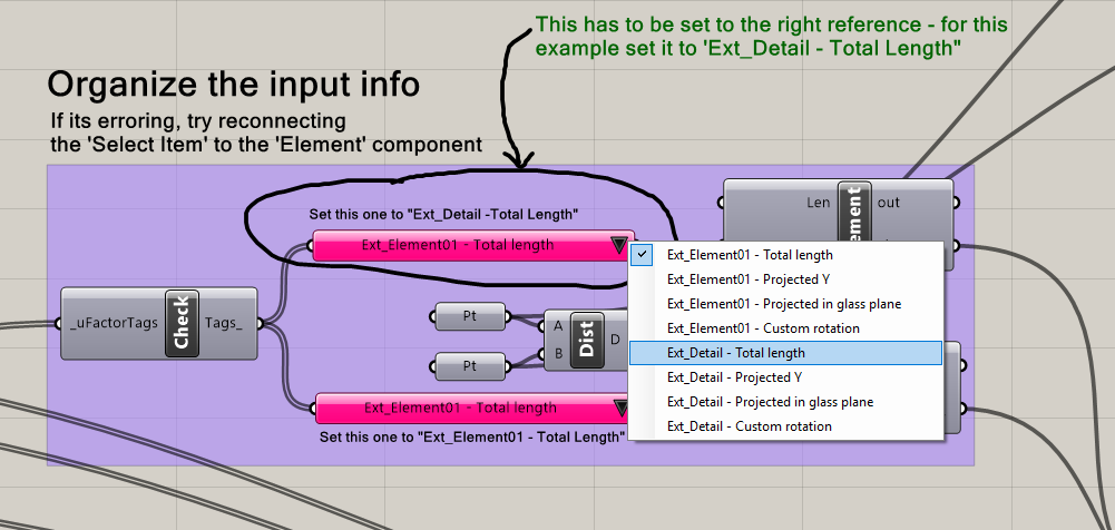
My apologies for the confusing set-up there - my setup is still pretty half-baked here and the reason you are getting the answer of -0.127 W/mk is because you need to update the ‘Select Item’ to the right input:
if you change that to 'Ext_Detail - Total Length" you should get the same answer as I show in the above description.
When I get a chance I’ll try a post an update to this workflow / component and make all more ‘automatic’ and flexible and hopefully I can find a nice way to remove that entire ‘reference length’ input section. Let me know if you still can’t get the same answer there though once you update that reference length.
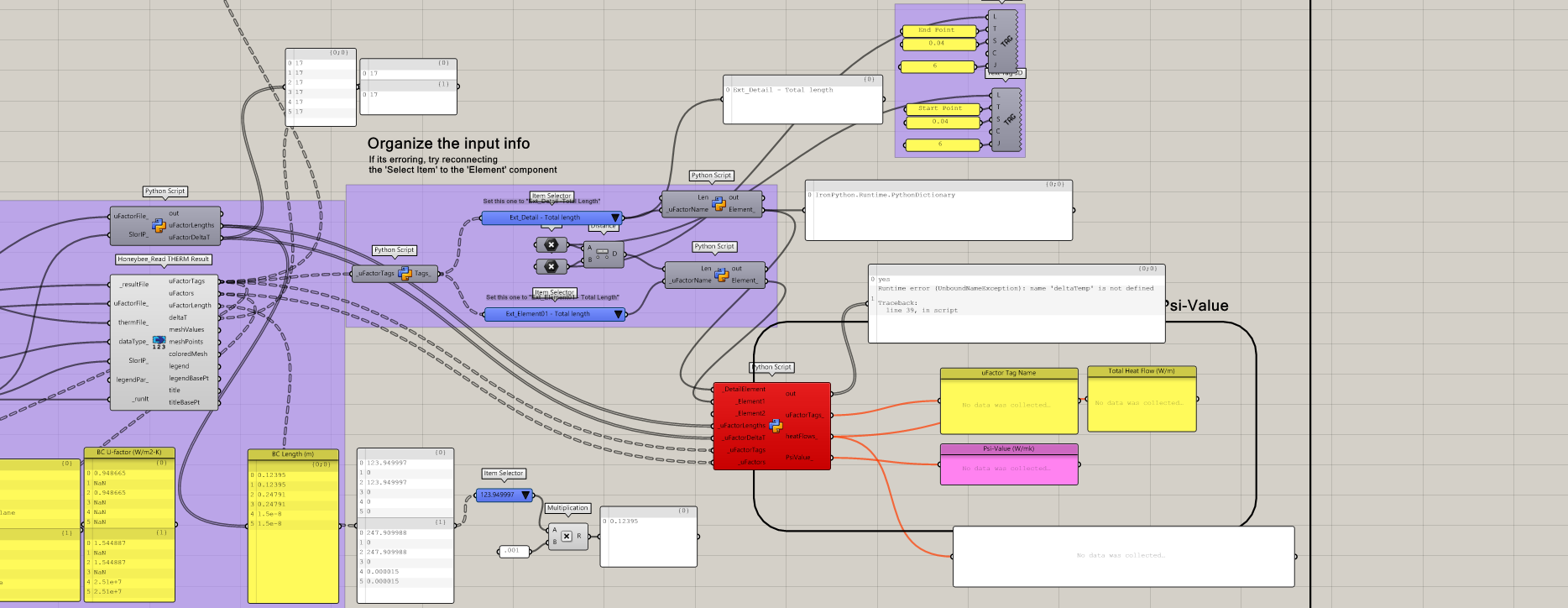
Hi Ed! Great work again with this examples. I came back to them with a project taht we wanted to look at some of our envelope conditions, however I noticed that the python script for the psi-value calculation is running into an error. I updated all of the components, but I wanted to see if you had any thoughts on the reason or if you had an updated workflow.
Thanks!
shoot! sorry about that. Sadly no, I haven’t had a chance to revisit this and clean up the workflow to be more robust just yet - its been sitting in my ‘to-do’ pile. I’ll try and carve out some time soon to dive back into it and clean it up though.
In any event - for now, if you can upload your GH file I’d be happy to take a look and see if I can sort out where the error is happening? Or if you can show what the specific error you are getting is?
Thanks for responding…we all have that “to do list”! Sorry, I thought I attached a file with the error, it seems to be with pulling the deltaT and ufactor lengths from your python script. @chris updated the honeybee read therm result component and it now has that information pulled from the therm file directly however that data is in meters. Ultimately, the script that calculates the heat flows and Psi values are running into an error with the deltaT conversion. Your script is merging the trees for the two simulations, which I get for sorting but it seems like the heat flow calculation is running into a loop error. I am not a python person, so I am probably wrong. Here is the updated attached file. Thanks for your help!
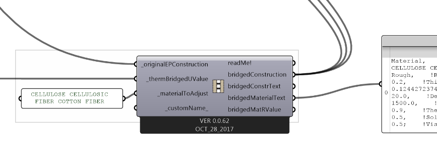
Ah! I get ya now. Yes I did update that workflow after @chris updated / modified the ‘readTHERM’ component to output the required information directly. But I think maybe I never posted that did I? Anyway - yes I’ve now modified these custom components and workflow to make it a lot simpler this time around (and to work with the updated readTHERM) and you can find the modified example attached to this message. A couple specific points:
Everything is ‘internalized’ for easy posting here, but it might be more clear how its put together if you bake out the Boundary Curves
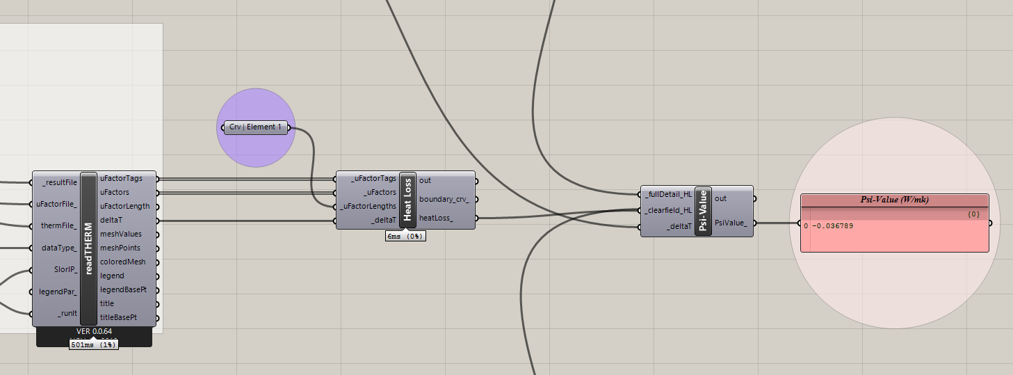
The only components now are a ‘Heat Loss’ and the ‘Psi-Calc’ and they are much simpler than before (I think). Hopefully they are more flexible now as well"
I’ve included 3 examples (same as before) and hopefully they are obvious - but of course give me a shout if anything in there is confusing.
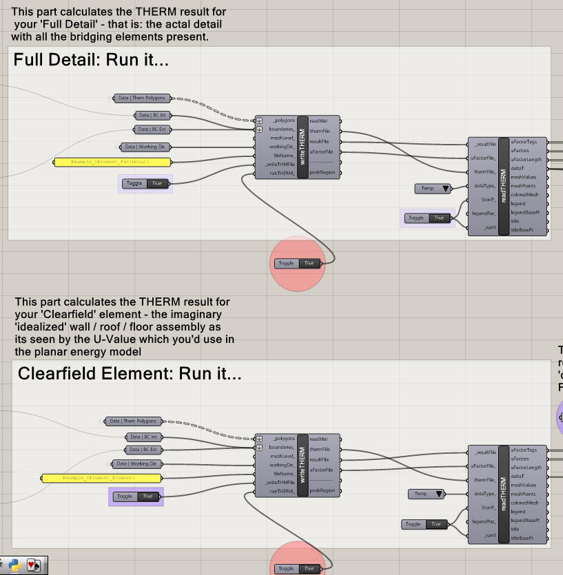
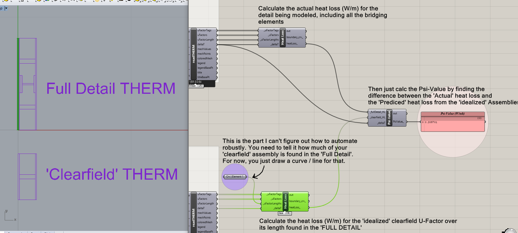
The workflow is now done using two (or three) separate THERM models for each detail. While this isn’t strictly needed - I think it makes it a lot more obvious what I’m doing here and makes it easier to track items / issues. So you do a ‘Full Detail’ THERM and a ‘Clearfield’ THERM, and then use those to calc the Psi-Value:
Once you run the two THERM simulations, the Psi-Value elements are quite simple: you just calc the total heat loss (SI inputs only for now) from each THERM result and compare them. To do that, add a ‘Heat Loss’ component after each ‘readTHERM’, then feed those into the ‘Psi Calc’ component:
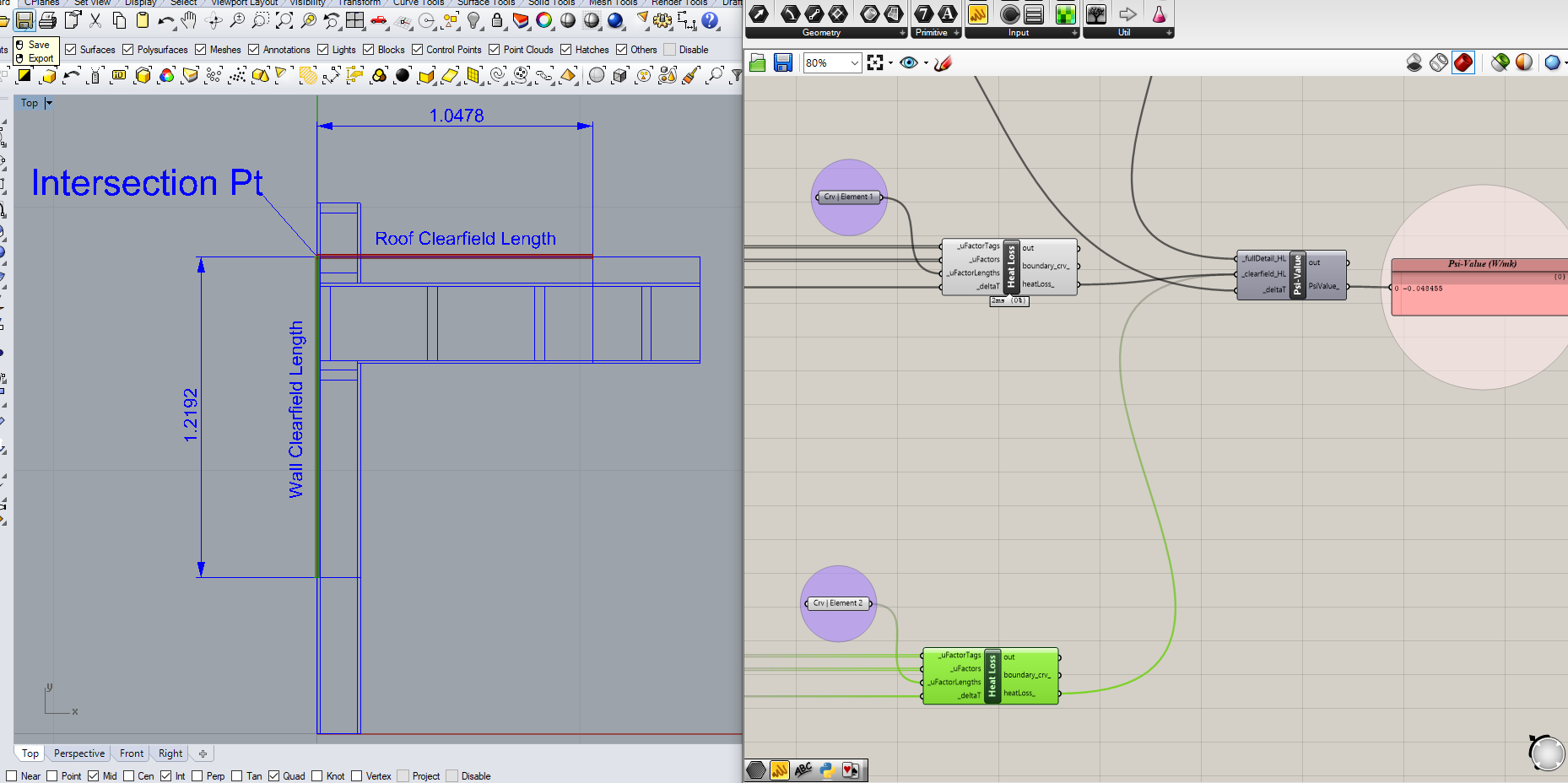
Note that the part I can’t quite yet sort out is how to automate the ‘Length’ being used to calc the ‘Predicted’ clearfield heat loss. There are just so many possible combinations that might be drawn, I can’t quite figure out how to determine it automatically from the already input values and geometry. I’ll keep thinking about it though cus’ I’d love for this to be easier / more error-proof. For now, I have it so you just describe the length either using numerical input (so just measure it and input the value) or using a ‘Curve’ input and it’ll calc the length itself:
I think this is most obvious in the ‘Parapet’ example here - the roof ‘clearfield’ and the wall ‘clearfield’ would intersect at some point which is not part of any of the input geometry, nor determinable from the input geometry without at least some small ‘tagging’ by the user:
If you knew something constant about the geometry (always would be X/Y, always would be vertical, etc…) there could be a way to pull all this from the input geometry. But that geometry could take so many forms that figuring out which clearfield goes where is tough. If you have any ideas for that though let me know and I can try and implement them and test?
at any rate: this should hopefully work for you now. I think I’ve updated all the HB components to the latest version of all and modified all my inputs to match. Take a look at the attached .gh file here though and let me know if you have any trouble with it.
Ed, thank you that’s great! Maybe I missed an updated file, but in any case, this will save time from writing out the equations. Thanks for sharing this work, its a great workflow! -Emmanuel